
The first machine used by GAP47 was made when we had to polish our 20′ mirror in 1992. The aim was to go through that phase of the work without excessive efforts, while retaining the characteristics and advantages of handwork (by limiting the defects coming from the repetitivity of mechanical movements). The principle that was chosen then was to opt for a pantograph which would increase muscular power.
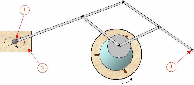
The pantograph’s arms are linked to one another by pin articulations. One end consists in a fixed pivot (3) . At the far end of the pantograph there is a handle (1) and a small wheel that may be rolled over a small table (2) . At the central articulation of the device there is a drive pin which transmits the movements to the lap. It is impossible to use this system with the mirror on top. The revolving table (supporting the mirror) is run by a 220v AC motor coming from an old supermarket cash desk conveyor belt. The speed of the mirror is 10 rpm and cannot be changed. There is a pedal to keep the motor running.
The second machine built at GAP47 is more recent (2006). It is an off-set Hindle-type machine with a double crank system. It will be used for the polishing of our current project of a 16′ mirror, and, as far as possible, for its figuring. Here are the principles that were paramount in its building :
- Two cranks with adjustable width, permitting a large choice of strokes.
- DC motors to prevent electric risks in wet surroundings. Moreover, these motors have variable torque thus contributing to a breach of coordination when the surfaces stick to each other. Besides, their rotation speed may be modified through simple changes in the electric tension. The drive arm can be lifted and its length is adjustable.
- One motor is dedicated to each rotation movement (the machine has three motors) in order to avoid the periodicity created by a single motor, connected through belts and spindles.
- Its volume is reduced and some features make the machine able to be easily stored away (the motor blocks may be simply detached) or even be used for other purposes (the table and the rotating plate are at the same height so that the machine can be used as an ordinary table).
Building an offset Draper-type polishing machine
 |
 |
 |
 |
|
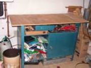
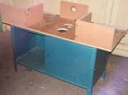
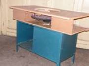
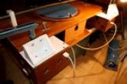
For a start : a half-forgotten workbench at the back of a garage . |
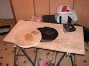
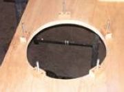
The turn-table is sawn off from the table top (on second thought, the 410mm diameter is a little too small). |
A second layer of plywood is glued to the turn-table to make it more rigid . |
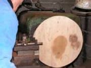
The side of the turn-table is aligned with the help of a lathe (not really indispensable). |
 |
 |
 |
 |
|
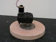
The turn-table fitted with a DC motor with its speed reducer |
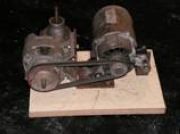
The two motor sets (12v DC motors from washing-machines) and their speed reducers (from the scrap yard). Their final speeds are 11 rpm and 9 rpm, respectively . |
The motor sets are independent blocks that can be easily separated from the rest of the machine . |
|
 |
 |
 |
 |
|
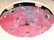
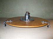
The turn-table speed reducer is screwed to a round plywood base . |
Five screw threads are fixed to the table-top around the opening, from under . |
The round plywood base is bolted to the underside of the table-top. Three little wheels are set at 120° angles . |
The turn-table is fitted to the reducer’s axle, in contact with the wheels. The height of the turn-table is adjusted thanks to the 5 screw threads . |
 |
 |
 |
 |
|
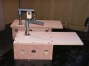
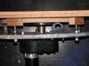
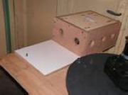
The metal sides and top of the work bench are opened for access . |
The different supports are placed into position in order to accommodate the top
|
The table-top is fixed to the supports together with its motor base for the turn-table . |
The motor blocks are screwed to the table top (using a screw thread as a rotating axle) . |
 |
 |
 |
 |
|
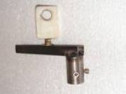
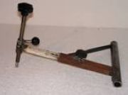
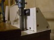
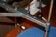
Crank number 1 with its adjustable crankpin .
|
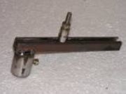
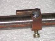
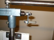
Crank number 2 with a teflon sliding-shaft holder fixed to the crankpin (the crankpin is adjustable) . |
The arm of the tool-holder device can be lifted. It is of adjustable length. One can see the vertical tool-driving pin . |
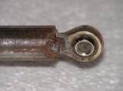
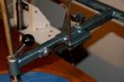
At the crank number 1 end of the link bar (connecting the two crank shafts) we find a spherical joint . |
 |
 |
 |
 |
|
On the link bar a stop is set that sustains the arm of the tool-holder device (to avoid possible shocks of the pin against the mirror) . |
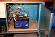
Electrical connections of the motors . |
Front panel with a switch for each motor . |
The power is provided by an accumulator (two batteries connected in series or in parallel depending on the speed needed). |
|
Accessories and various late improvements |
|||
 |
 |
 |
 |
|
Bearings for the crank axles to relieve the strains on the speed reducers’ bearings . |
Small hand-crank for an easy adjustment of the offset crank |
Rack on the arm of the tool-holder device to adjust the length of the offset effect. |
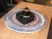
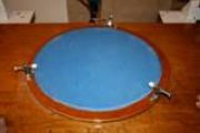
Greater diameter of the turn-table together with adjustable 120° side-holders . |
 |
 |
 |
 |
|
Round tray with a socket to hold the mirror when working with mirror on top . |
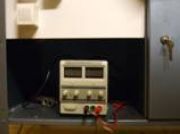
Adjustable electric transformer (from 0V to 30V) for the right crank motor . |
Graduations for a precise adjustment of the cranks. |
Graduation for the adjustment of the offset effect arm. |